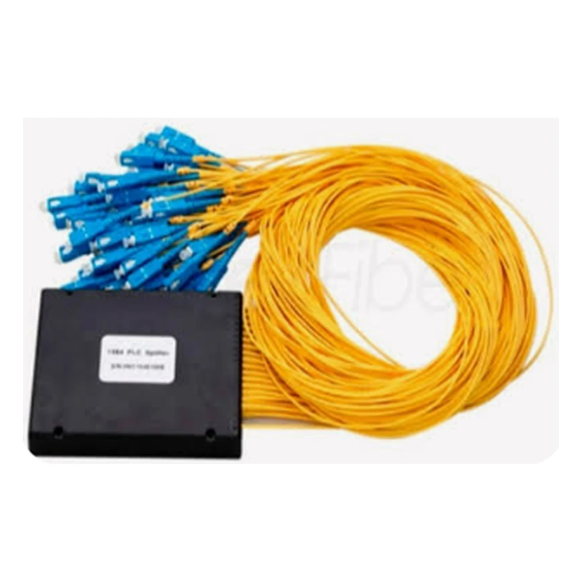
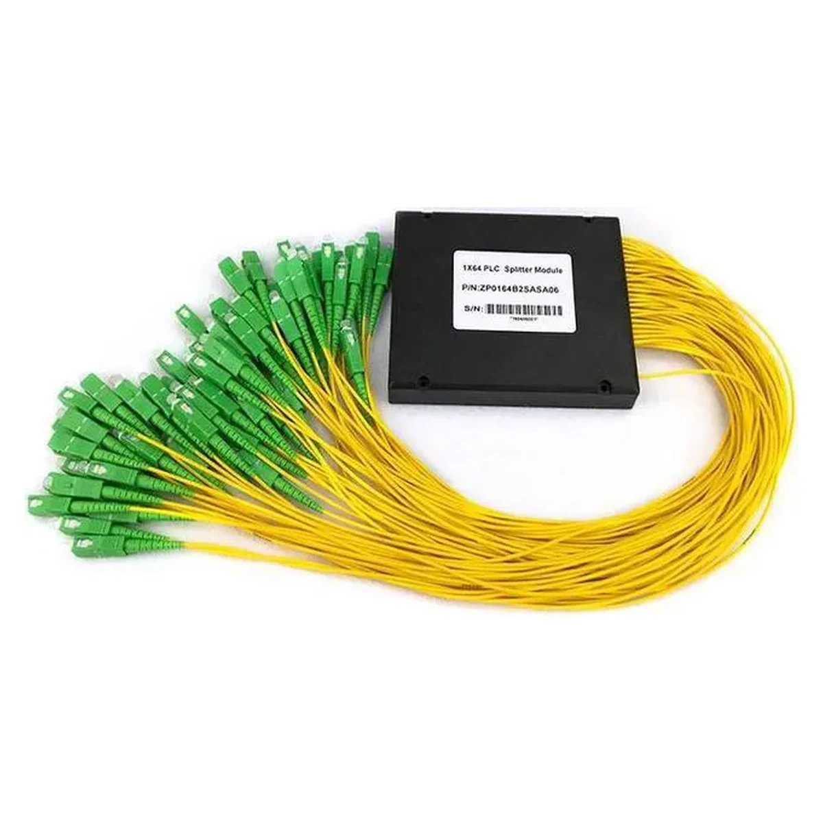
PLC Splitter 1×64 SC/APC
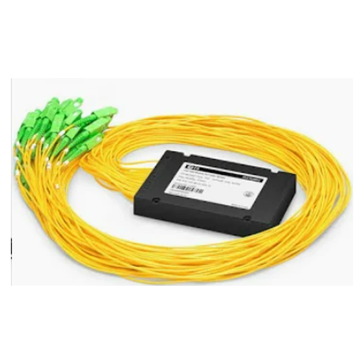
1×64 splitter in an ABS box, SC/APC connectors, for GPON networks
Specifications
- Type
- PLC splitter
- Split ratio
- 1×64
- Band
- 1260–1650 nm
- Version
- ABS cassette, color-coded pigtails
- Connectors
- SC/APC (8°)
- Insertion loss
- ≈20.5 dB
Description
The 1×64 PLC splitter with SC/APC connectors is a planar splitter of maximum density for carrier GPON networks: one OLT port serves up to 64 subscribers. The ABS plastic cassette with color-coded pigtails installs into fiber patch panels and distribution cabinets. The 1260–1650 nm working range covers all PON wavelengths, and the split shows low non-uniformity between outputs.
The green APC connectors with an 8° angled polish keep back reflections to a minimum — a critical requirement for stable PON operation. Planar technology divides the signal evenly and predictably, which simplifies network calculation. The insertion loss of about 20.5 dB is written into the optical budget of the line at the design stage. The splitter is available from our warehouse in Tashkent — we can help calculate the branch budget and select the accompanying optics.
Advantages
- Up to 64 subscribers from a single OLT port
- SC/APC connectors with 8° polish — minimal back reflections
- ABS cassette for patch panels and distribution cabinets
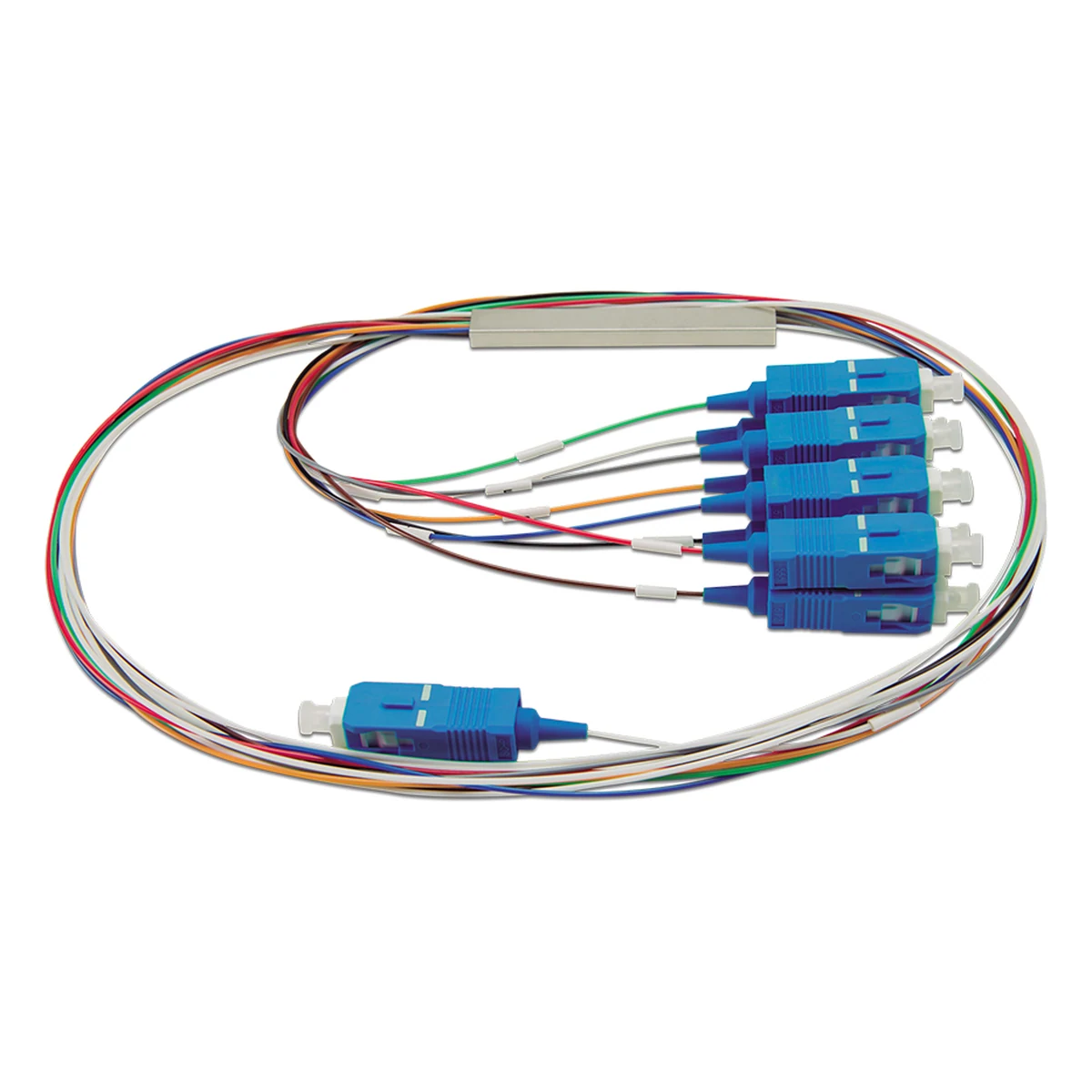
- Color-coded pigtails simplify splicing and labeling
- Wide working range of 1260–1650 nm
Applications
- Carrier GPON networks
- Neighborhood distribution cabinets
- Networks of villages and residential complexes
- FTTH access nodes
Mounting and connection
The splitter cassette is fixed in a patch panel or cabinet, the input pigtail is spliced or connected to the line from the OLT, and the outputs are distributed across subscriber directions. The color coding of the pigtails lets you keep a connection log without testing every fiber. Before each connection the connector end faces are cleaned, and unused ports are closed with dust caps — cleanliness is critical for loss. APC mates only with APC: mixing with UPC causes a jump in loss and reflections. A typical layout is a splitter in a neighborhood cabinet, from which subscriber lines fan out to the buildings.
Frequently asked questions
When is a 1×64 split chosen?
Why are the connectors green?
What is the loss of a 1×64 splitter?
Can the splitter be cascaded?
Product reviews
Questions & answers